
OSSM Flagship PCB
A 75 x 75 mm controller PCB that sits in an 85 mm round housing. It takes a 36 V supply, powers and commands the motor, and talks to the outside world through an ESP32-P4 with a stacked ESP32-C6.
It runs Nucleus. The design is under CERN-OHL-S-2.0.
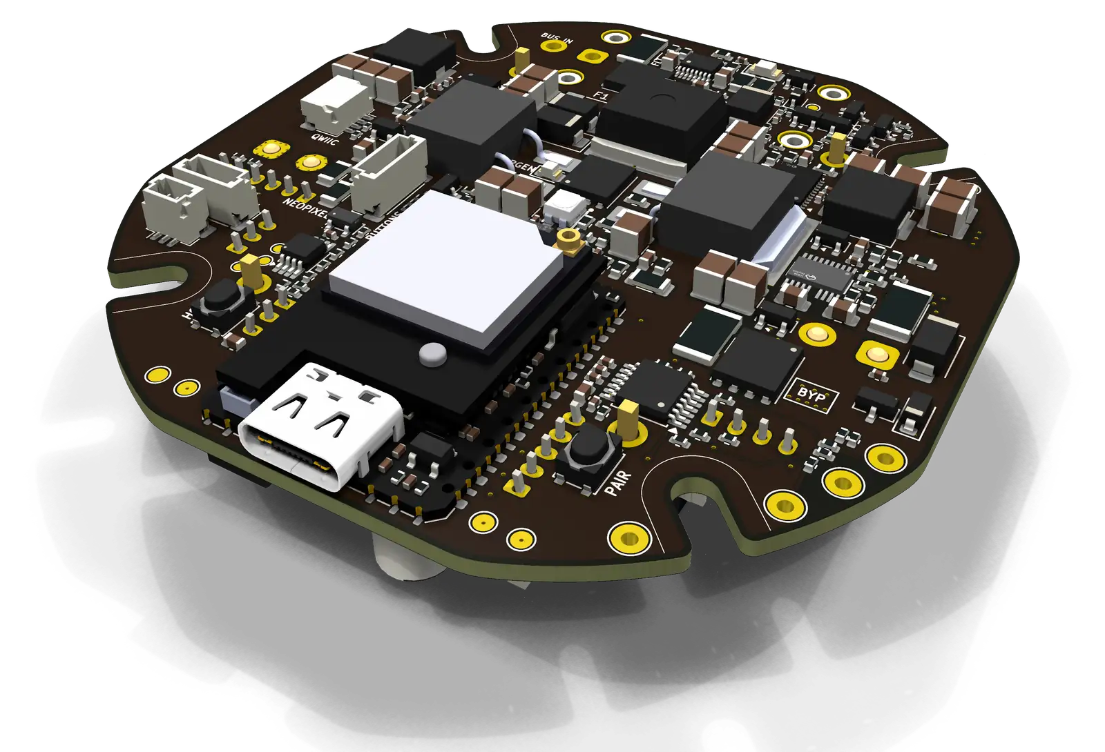
Status WIP
These renders come straight from the KiCad project as it stands today, so parts can still move. No fabrication files are published and no boards are for sale.
What's in the repo
The KiCad 10 project, the parts list, the stackup and a dated ledger of design decisions. Where FEATURES.md and SPEC.md disagree, SPEC.md wins.
Main parts
Hover or tap a number to see what that part does.
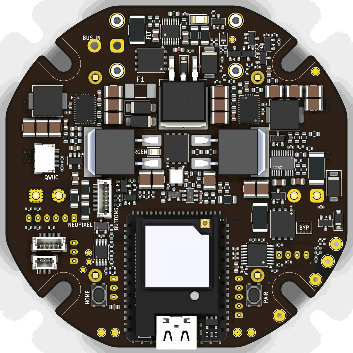 ESP32-P4 module (main processor)
Surge stopper (input protection)
Input power FET (surge stopper)
Input fuse
Regen load resistors (pair)
Regen clamp switch
Motor switch (smart high-side)
Quadrature buffer to the motor
RS485 transceiver (motor comms)
HOME button
PAIR button
Status LED
Qwiic / STEMMA QT port
5 V buck converter
- ESP32-P4 module (main processor)M5Stack Stamp-P4 with a Stamp-AddOn C6 stacked on top for Wi-Fi and BLE. Its low-power core generates the quadrature motion signal.
- Surge stopper (input protection)LTC4364 rides through input spikes at 51.5 V, limits current to about 25 A, blocks reverse polarity and reverse current, and retries about once a second after a fault, so regen never reaches the power supply.
- Input power FET (surge stopper)One of the back-to-back FETs the surge stopper drives: it carries the whole bus and opens on any fault.
- Input fuse15 A soldered fuse, the last-resort backstop against a dead short from a stiff supply.
- Regen load resistors (pair)Two 15 ohm power resistors in parallel (7.5 ohm) that burn off the energy a back-driven motor pumps into the bus; each handles about 6.8 W mean and 132 W bursts at worst case.
- Regen clamp switchConnects the resistors across the bus above 44.5 V and releases below 43.2 V, before the supply's overvoltage trip, with no firmware involved.
- Motor switch (smart high-side)TPS48111 gates bus power to the motor XT30: soft pre-charge of the motor, latching trips at 15.2 A (10 ms) and 30 A (1.2 us), and the E-stop or an overvoltage cuts it in hardware.
- Quadrature buffer to the motor74AHCT125 lifts the P4's A/B pulses to 5 V for the motor's opto inputs.
- RS485 transceiver (motor comms)THVD1450 carries Modbus to the motor, with ESD protection and an optional 120 ohm termination; the motor's position comes back over it.
- Status LEDAddressable status LED, level-shifted to 5 V so the colors stay reliable.
- Qwiic / STEMMA QT portJST SH port on its own I2C bus: plug in small screens and sensors without soldering.
- 5 V buck converterLM76003 synchronous buck (3.5 A) that feeds the P4 module and the accessory 3.3 V regulator; a twin makes 12 V for the fan, clamp and pump.
Top and bottom
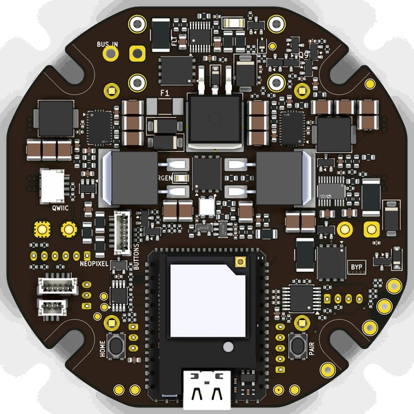
Top: compute and the power stage 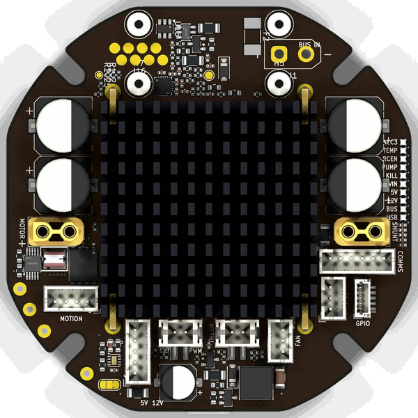
Bottom: the 40 x 40 mm heatsink and most connectors
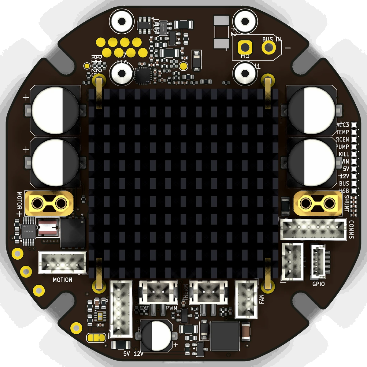
Motor interface
The target motor is the YZ 60AIM40F (200 W). The PCB is also built to drive the 350 W 60AIM40. It talks to the motor three ways.
- Quadrature
A and B come from the P4's low-power core, buffered to 5 V, straight into the motor's opto inputs.
- RS485 Modbus
Used for reads such as position. The PCB also supplies the motor's 485-side 5 V, so one cable carries signal and power for the motor's comms side.
- Alarm and ready inputs
The motor's alarm and ready lines go to the P4, so a motor fault reaches the firmware directly.
Hardware protection
- 36VBus in, 10 A continuous to the motor
A 15 A fuse is the last-resort backstop against a dead short.
- 44.5VRegen clamp, in hardware
On at 44.5 V, off at 43.2 V, with a port for an external brake resistor. It works without the firmware running.
- Surge stopper
Blocks reverse polarity and reverse current, so regen from a motor coasting down never reaches the power supply or trips its overvoltage latch.
- Motor switch and power monitor
Pre-charge, latching overcurrent trips, and a monitor on a four-terminal shunt that reports bus voltage, current, power and energy, so the firmware can see the load and back off before anything trips.
- External E-stop input
Pressing the button or unplugging it cuts motor power in hardware.
Board features
- Compute
M5Stack Stamp-P4 (ESP32-P4) with a Stamp-AddOn C6 stacked on top for Wi-Fi and BLE.
- HOME and PAIR
Two buttons and one status LED. No reset button.
- Fan and temperature
A fan header with speed control and tach, and a thermistor input.
- Optional accessory outputs
A fused 12 V pump output with a PWM signal, an external PWM output, a Neopixel chain, a Qwiic port and a GPIO header. Anything smarter than a switch belongs on its own board, over Valence (see Isotope).
- 6layers75 x 75 mm, heatsink on the back
Parts on both sides except under the 40 x 40 mm heatsink, which sits under the power parts. Three XT30 power connectors, JST XH for signals.
Related
Nucleus is the PCB's firmware, and Valence is the protocol its hub uses. The diagrams show the connections, and Components lists every part.
Repo · Features · Decisions ledger · Nucleus · Diagrams